July 2008 Edition
shop talk
Simple steps to avoid GD&T headaches

‘Entities should not be multiplied beyond necessity.’ — Ockham’s razor
By Richard Clark
If your facility is anything like many of the industrial facilities I have
worked with in the "real world," then common GD&T problems might occasionally
turn into a "free-for-all."
A machinist looks at a part drawing a certain way because of how he or she
sets up the machine in order to make the part. The engineer views the part in a
perfect CAD world. And the quality inspector is trying to re-create the drawing
to confirm that each feature is correct, when measured exactly as the drawing
"calls" out each feature.
The challenge for your facility is that individuals of many different GD&T
knowledge levels must not only co-exist, but work toward a common goal without
losing their minds. I suggest a simple, yet highly strategic Five-Step process
to follow.
- Define it
- Find it
- Plan it
- Test it
- Measure it
To begin, I would create a brainstorming group of four to five people from as
many job functions as you have in your equation. A nice blend would be an
engineer, a machinist and two inspectors.
Did I forget anyone? Yes. Always include someone from your management team.
It will save a lot of explaining later.
 The
first step of the investigation is to define the GD&T characteristic. There are
many sources (or references) you can obtain if you don’t already have a GD&T
reference. According to my colleagues at Technical Consultants Inc., parallelism
is defined as the condition of a surface, line, or axis, which is equidistant at
all points from a datum plane or axis.
What is really helpful for the team to look for within the definition is the
"this on the drawing means this on a part" explanation.
Once the definition is clear, the team should be able to find the
characteristic on one of your part drawings. The natural response now would be
to measure your part but I don’t recommend this just yet. If you measure now and
your reading doesn’t come out like you think it should, you’re right back where
you started: Is the part bad, is the proposed measuring method incorrect, or is
our understanding of the GD&T not correct? (…and nobody trusts the CMM).
This is why I recommend the next step be to plan it. You may have several
measurement equipment options so it’s important to choose the best option for
your situation. To determine this, I suggest testing a part of a known value. As
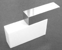
an example, if you need to confirm parallelism of two faces using a CMM, you
could wring two gage blocks together (slightly offset).
You could test your measurement method by measuring the top face of one block
and defining it as the datum and then measuring the top face of the second block
and "asking" the CMM to calculate the parallelism. These should be nearly
perfectly parallel.
If this were the result, I would say the measurement method passes the test.
This will also give an idea of what the best result you’ll get might be. If you
found these gage blocks to be out of parallel by 0.001mm (just under 50
millionths of an inch) at a reference length of 25mm, that lets you know about
what your part might read, even if it were perfect.
Once this cycle is completed, you’re set. When you measure the characteristic
in the future and someone questions your method, you have a test ready to use.
Richard Clark is a quality systems consultant from Portland, IN. To order
a copy of his book "Exposing the Myths of Industrial Precision Measurement" or
to offer feedback, e-mail
rcmetrology@yahoo.com
What do you think?
Will the information in this article increase efficiency or
save time, money, or effort? Let us know by e-mail from our website at
www.ToolingandProduction.com or e-mail the editor at
dseeds@nelsonpub.com.
editor's blogs

Off the Toolpath
EASTEC marks 30th show with spotlight on medical devices
The recession hasn’t stopped business, if the activity at the EASTEC Advanced Productivity Exposition is to judge. The show, in its 30th year, drew 570 exhibitors, down from 608 in 2008 and 650 in 2007. About 15,000 attendees pre-registered. Last year’s show tallied 14,000 attendees. The largest industrial tool trade show on the East Coast, EASTEC was held May19-21 in West Springfield, MA.
by Dennis Seeds, Editor-in-Chief
digital edition
On target
For a new generation of parts, automated centerless grinding fills the bill
The taper test
Prototype fixture finds the reason why vexing toolholder wear marks appear
Watchful eye keeps tabs on 575 machine tools
Aerospace supplier sees new productivity heights, lower costs
From 12 hrs to 25 mins
Giant steps for faster cavity hogging, square-offs follow re-tooling